Wireless charging has revolutionized how we power our devices. For engineering students, understanding the technical intricacies behind this technology is both fascinating and essential. This blog will explore the principles, components, and standards of wireless charging in detail.
Fundamental Principles
At the core of wireless charging is the concept of electromagnetic induction and resonant inductive coupling. These principles enable the transfer of energy without direct electrical contact.
What is Electromagnetic Induction?
Electromagnetic induction is the process by which a changing magnetic field within a coil of wire induces an electromotive force (EMF) across the ends of the coil.
When the transmitter coil in the charging pad is energized with an alternating current (AC), it generates a time-varying magnetic field. This magnetic field is confined within a specific area around the coil, influenced by factors like coil geometry and current frequency. When a receiver coil in a device is placed within this magnetic field, the changing magnetic flux induces an AC voltage across the receiver coil. This induced voltage can drive a current through a load connected to the receiver coil, effectively transferring power wirelessly. This principle, discovered by Michael Faraday, forms the basis of wireless charging technology.
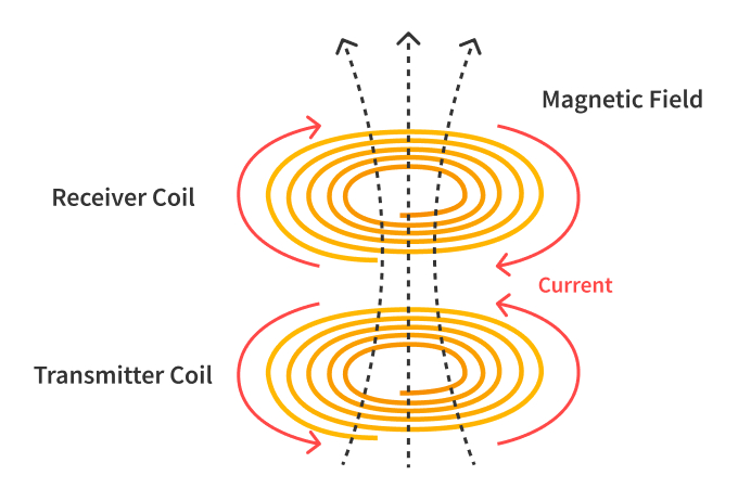 Figure 1: Diagram of Electromagnetic Induction with Transmitter and Receiver Coils
Resonant Inductive Coupling
Resonant inductive coupling is the near-field wireless transmission of electrical energy between two coils, coupled by a magnetic field. Both coils must be tuned to resonate at the same frequency. Power is transferred via magnetic fields between two resonant-tuned circuits: one in the transmitter and one in the receiver, as illustrated in Figure 2 below. Each resonant circuit consists of a coil connected to a capacitor. To achieve increased coupling and maximum power transfer, the two coils must be tuned at the same resonant frequency. We also need a high Q-factor of the coils and a significantly high coupling factor as well.
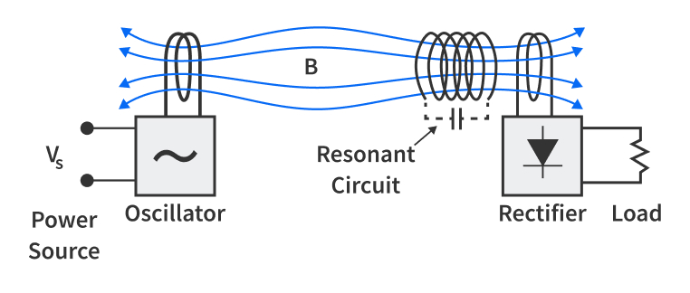 Figure 2: Resonant Inductive Coupling
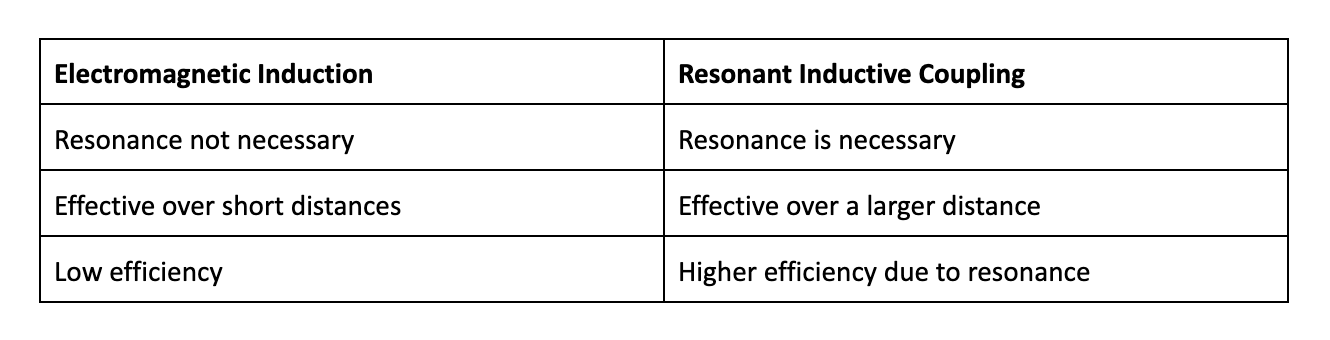
If you are wondering how is that different from the concept of electromagnetic induction that we just discussed, here are a few key differences
Electrical resonance occurs in an electric circuit at a particular resonance frequency, where the imaginary parts of impedances or admittances of circuit elements are equal in magnitude but opposite in phase, effectively nulling each other out. This results in the circuit exhibiting purely resistive impedance at resonance, often seen in LC and RLC circuits.
If we consider the resonance in a circuit involving capacitors and inductors, it primarily occurs because the collapsing magnetic field in the inductor generates an electric current in its windings, which charges the capacitor. Then, the discharging capacitor provides an electric current that rebuilds the magnetic field in the inductor. This process repeats continuously, creating a resonant frequency as energy oscillates between the inductor and capacitor.
Resonance tuning is achieved by designing the coils with specific inductance (L) and capacitance (C) values to resonate at a particular frequency, given by the formula:
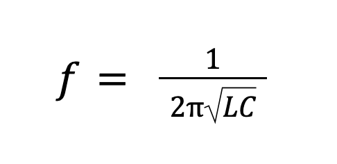
When the coils are at resonance, the energy transfer between them is maximized.
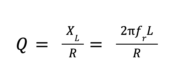
The Q-factor of a coil measures how good the inductor is at storing energy. It primarily depends on the shape and size of the coil and the materials used. It is an important parameter to take care of, because every coil has a small resistance in addition to its inductance. The lower the value of this resistance (R), the higher the Q factor of the coil. Values for the Q-factor typically range between 10 and 100. A Q-factor below ten is generally useless.
The quality factor (Q) at the operating frequency (ω) is defined as:
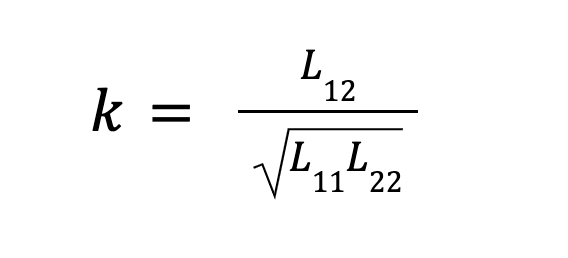
The efficiency of power transfer is heavily influenced by the magnetic coupling factor (k), which represents how efficiently the magnetic field of the transmitter couples with the receiver. This factor depends on coil alignment, distance, and orientation. A higher coupling factor indicates better energy transfer.
The coupling factor (k) is a dimensionless value that defines the interaction between the primary and secondary coils of any wireless power transfer system. It should be between zero and one, with one indicating perfect coupling, meaning all flux generated penetrates the receiver coil. Common coupling factors range from 0.32 to 0.65. A negative coupling factor indicates the capture of magnetic flux from behind, leading to opposite-phase voltage induction. The coupling factor is given by:
Detailed Wireless Charging Process
The wireless charging process involves several critical steps, each with important components and mechanisms.
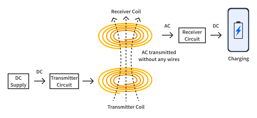 Figure 3: Block Diagram of Wireless Charging System
Figure 3 illustrates the process of wireless mobile battery charging from the input at the charger to the output at the mobile phone. This process involves a wireless power transmitter section and a wireless power receiver section.
Transmitter Section
The transmitter section includes the following components:
- Power Supply: Provides the necessary DC voltage.
- Transmitter Circuit: Converts the DC voltage to a high-frequency AC voltage.
- Transmitter Coil: Converts the high-frequency AC voltage into an alternating magnetic field.
Receiver Section
The receiver section consists of:
- Receiver Coil: Captures the alternating magnetic field and converts it back into AC voltage through induction.
- Receiver Rectifier Circuit: Converts the induced AC voltage to DC voltage.
- Voltage Regulator IC: Ensures the DC voltage is suitable for charging the mobile phone battery.
- Mobile Phone Battery: The final recipient of the converted and regulated DC power.
Energy Transmission Process
The wireless mobile battery charger works through inductive coupling, which involves several steps. First, the transmitter coil generates a high-frequency AC signal that creates an alternating magnetic field. This alternating magnetic field is crucial for energy transfer as it radiates around the transmitter coil. The receiver coil, when placed within the range of this magnetic field, captures the energy and induces an AC voltage within its windings through electromagnetic induction. This induced AC voltage is then rectified to DC by the receiver's rectifier circuit to ensure compatibility with the electronic components of the mobile phone. Subsequently, the voltage regulator adjusts this DC voltage to a level suitable for the mobile phone battery, preventing overcharging and ensuring a steady flow of power.
Finally, the adjusted DC voltage charges the mobile phone battery, providing a seamless and efficient energy transfer process that powers the device without the need for physical connectors. This process not only enhances the user experience by offering convenience but also reduces wear and tear on charging ports, contributing to the longevity of mobile devices.
If you still need help understanding the process, we recommend checking out what our Friends at CircuitBread have to say about wireless charging in their blog: How does Wireless Power Transmission work?. Not only this, you’ll find several other tutorials on their website which deal with the components involved in the wireless charging process.
Wireless Charging Standards
There are multiple standards that govern wireless charging technology to ensure safety and compatibility. The most popular standards are as follows:
Qi (pronounced "chee")
Developed by the Wireless Power Consortium (WPC), Qi is the most widely adopted wireless charging standard. It supports both low-power (up to 30 watts) and high-power (up to 1 kilowatt) charging applications. Qi ensures interoperability between different devices and chargers, making it a popular choice for smartphones and other small electronic devices.
AirFuel Alliance
The AirFuel Alliance, formed by the merger of the Alliance for Wireless Power (A4WP) and the Power Matters Alliance (PMA), promotes two wireless charging technologies: resonant inductive and radio frequency (RF) charging. AirFuel's resonant technology allows for greater spatial freedom and multiple device charging, while RF charging supports charging over longer distances.
Efficiency Considerations
Wireless charging systems must be designed to minimize energy loss and maximize efficiency. Key factors influencing efficiency include coil design, alignment, frequency, and heat management. Optimizing the shape, size, and materials of the coils can significantly improve efficiency.
Proper alignment of the transmitter and receiver coils ensures optimal coupling and energy transfer. The operating frequency affects both the efficiency and range of wireless charging, with higher frequencies offering better efficiency but potentially requiring more precise alignment. Additionally, efficient wireless charging systems must manage heat generation to prevent energy loss and ensure safe operation.
Applications of Wireless Charging
We already know that wireless charging is most popular in the sector of consumer electronics. From laptops to wearable devices, wireless charging provides the convenience of cable-free power transfer and reduces cable clutter, making device management simpler and more efficient. But this isn’t all. In the future, we can see several other interesting uses of wireless charging.
We can leverage the advantages offered by wireless charging by using them in electric vehicle charging. Imagine not having to jump out of your car to get it charged up. You simply drive your car over a large charging pad on the side of a highway and your car starts charging. There won’t be any need for physical connectors at all! Even in medical settings, wireless charging reduces infection risks and provides isolation of medical devices by eliminating the need for cables and connectors. Additionally, in industrial settings, wireless power transfer can be utilized to power equipment and sensors in hard-to-reach or hazardous areas, ensuring continuous operation and improving safety by eliminating the need for physical connections.
As we continue to innovate and refine wireless charging technology, its applications will expand, offering new possibilities and transforming how we interact with our electronic devices.
 contact us:
 EN
EN
 English
 Chinese
 Italiano
 Portuguese
 Deutschland
 French
 Russian
 Japanese
 Turkish
 Korean
 Spanish
 my account & orders

